Using lego to build a device lab
By Mike Street
Making sure the websites we build work across a myriad of devices is paramount during the build process at Liquid Light. This is to ensure the user experience and functionality works across a range of devices and browsers.
Because of this, we have curated a range of devices to test our websites on - along with a copy of Ghostlab we can make sure websites look great no matter what your browser size or device.
Being able to see all the devices (as our device lab grew) was becoming more of a struggle the more devices we got, so much so that our front-end developer, Mike, managed to hack together a makeshift stand using just a MacBook Pro box and some cardboard. It served us well, but as you can see - we outgrew it.
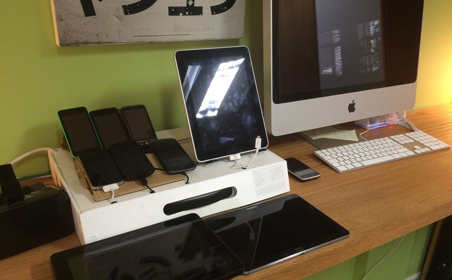
Our old DIY device lab had seen better days.
Seeing the Ghostlab Device Lab stand made us envious. Being able to see all the screens and for them to be correctly supported was great, but for the amount of devices we have, the stand wasn’t big enough. Doing some research and looking round at what other agencies had got us thinking - and it was the findings, plus the Ghostlab inspiration that encouraged us to create our own.
Research
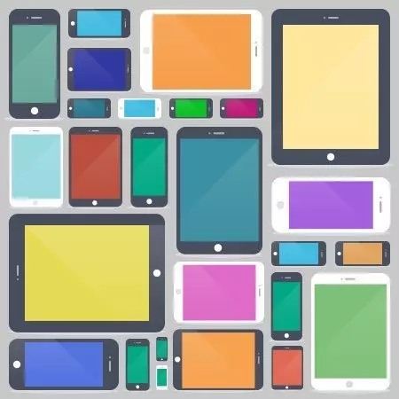
We started our research by seeing when else was out there - finding examples from Etsy and several open device labs gave us some ideas of how we could make ours.
There are several photos online but not many blogs about how to go about making one yourself (although since we’ve made ours, this pocket guide of “Building a Device Lab” has been published online.)
Planning
Armed with our research, we set about thinking about the design. We settled on a lego based system similar to Hamburg - allowing us to reconfigure it based on what devices we had at the time - it also means no trickery is needed with shelves and makes the build fairly simple.
The next trick was to work out the angle of the stand. This was done very scientifically - which really involved holding up one of the pictures in the office, saying “that will do” and measuring the angles.
The angle we worked out was 75.7˚ (which we rounded up to 76˚ for ease of maths!). We also worked out we would just need 3 bits of wood - the main back and two support pieces.
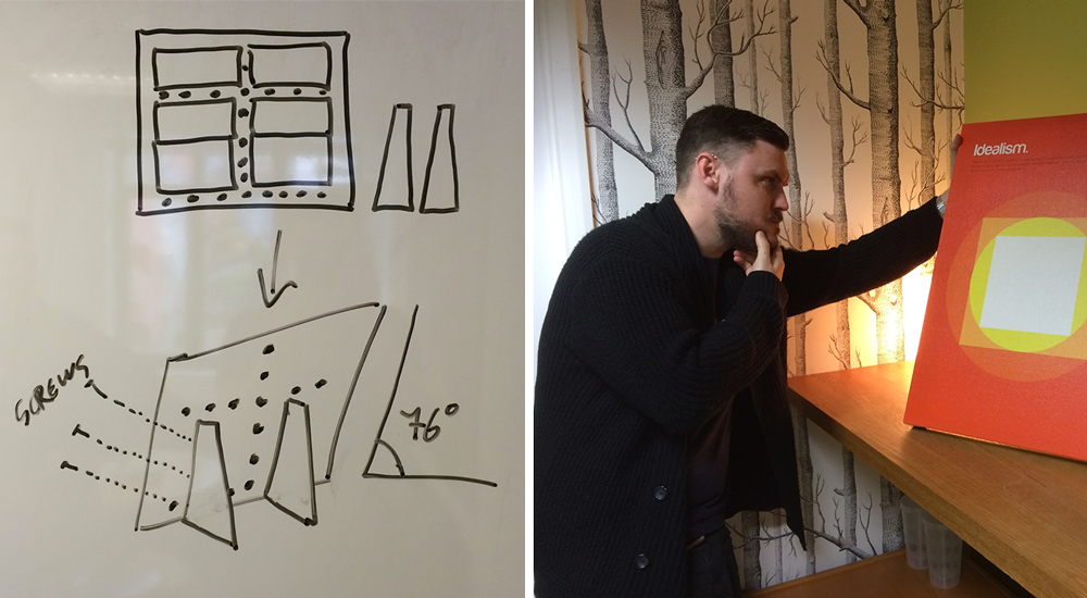
Calculating the correct angle had us scratching our heads.
Design
The next step was to jump into illustrator and create a diagram to scale. Not only this this help us optimise how much wood we needed, but we were then able to pass that to the wood shop to cut for us (yes, we got someone else to cut the wood for us).
We decided on 1 inch (25.4mm) thick wood for the main board, and ¾ inch (19mm) wood for the supports. This was thick enough for screws to go into the supports without splitting the wood.
You can download a copy of our Device Lab Plans.
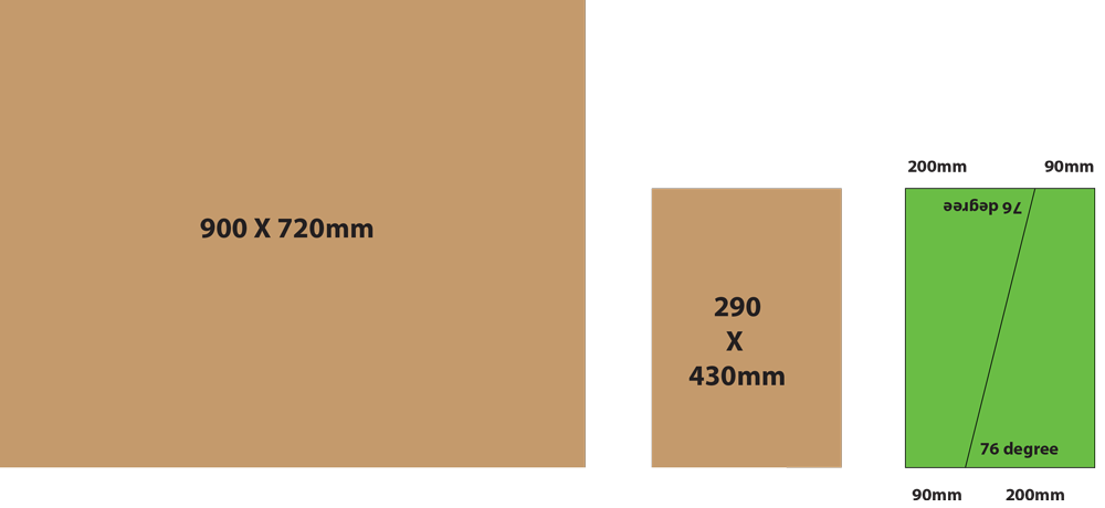
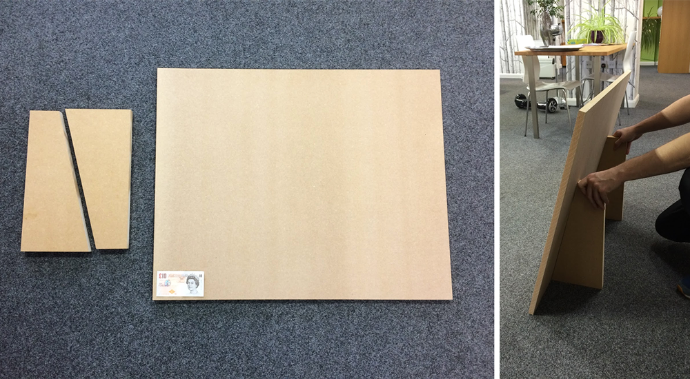
Our plans and the cut out pieces of MDF.
Preparation
With the wood cut, the last thing we needed to do before the build was to purchase was some Lego backboards. We decided to go for 6 rectangular boards (48 x 24 studs) as this gave us the flexibility for layout. We bought our boards from eBay, and they aren't "official Lego but they do the job. In the end, we decided on two boards separated at the top (for smaller devices), with the remaining four at the bottom close together for tablets. We used Lego to ensure the distance between the boards was compatible with being bridged between - should we need to.
We also allowed for several holes (13 in total) to help us with cable management for the devices.
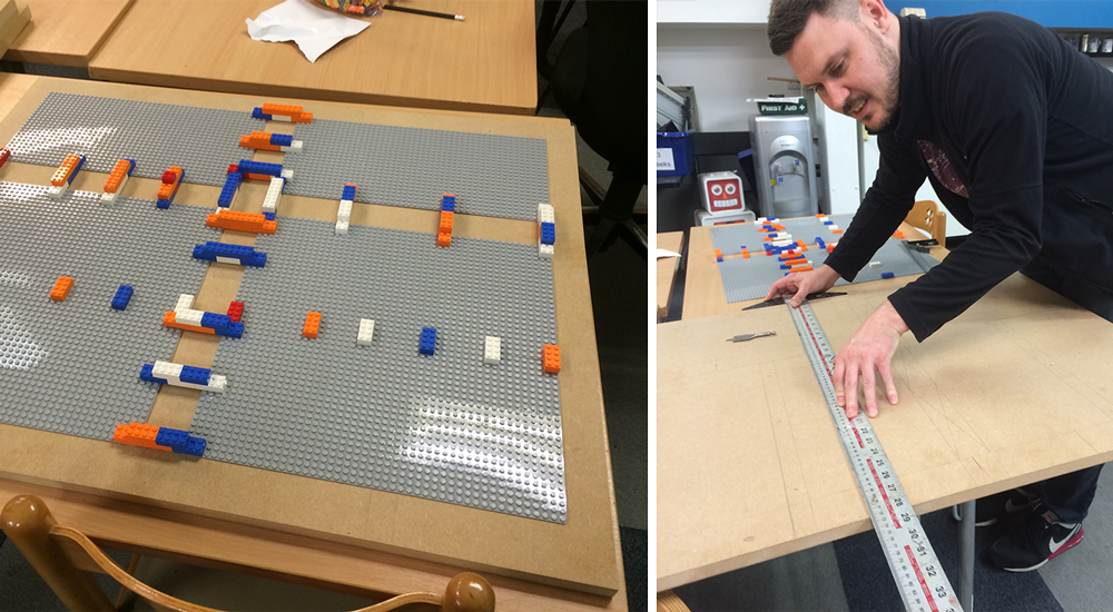
Using lego to ensure the boards were correctly spaced and marking out where the holes would go.
Implementation
We headed off to Build Brighton, our local makerspace to build the Device Lab. This has several tools (plus a spray booth) which meant we could build the lab more easily.
We started off placing the Lego boards on the backing wood and trace around them - this gave us an outline of where the boards would go. From here, we could then work out spacing and mark up where the cable holes would be placed. After drilling the cable holes, we created 6 pilot holes for the feet - these would be hidden behind the boards and so, were countersunk to avoid any interference.
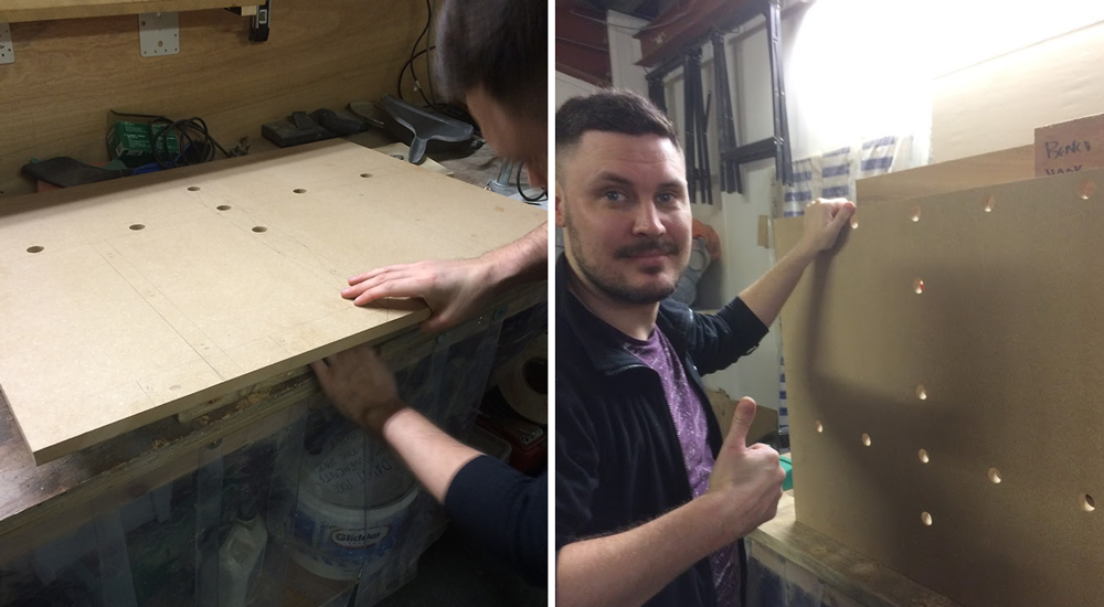
Holes all drilled, ready to assemble.
After constructing the stand and screwing the legs on, we headed down to the spray booth to begin painting. We had picked up a couple of spray cans of primer and black paint (to avoid brush strokes) and began covering. This was the longest part of the day - waiting for the paint to dry between coats. We did 2 coats of primer followed by 2 coats of black paint.
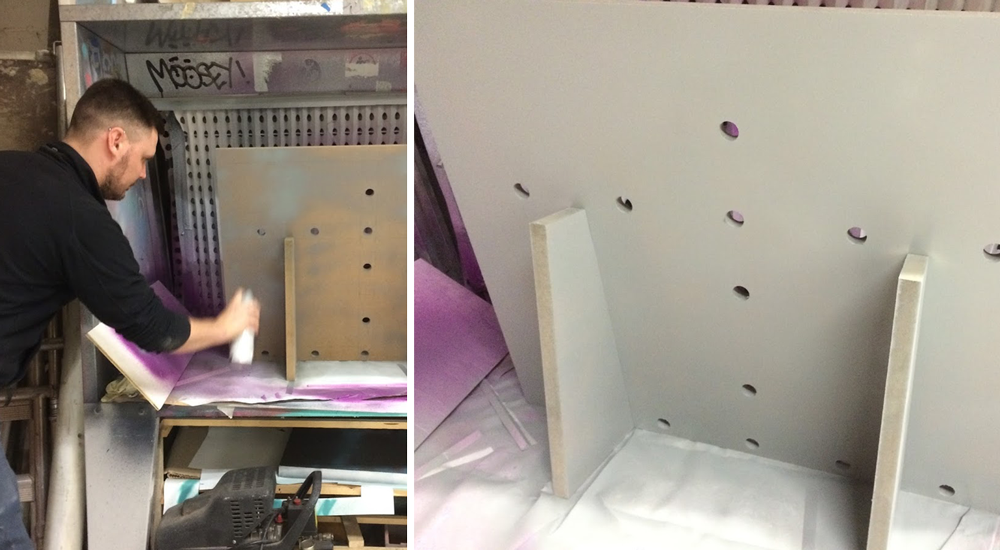
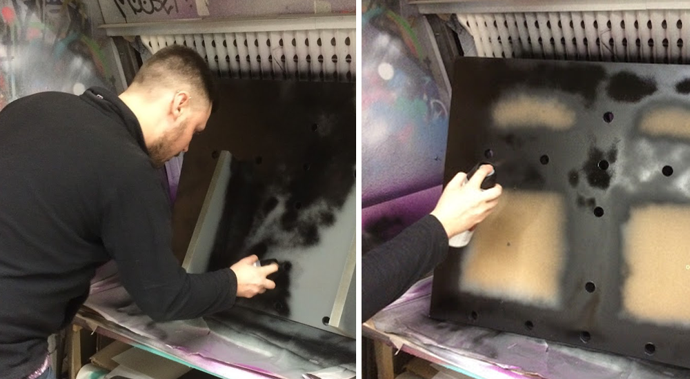
Priming the assembled device lab and then adding a top coat of black spray paint.
While we were waiting for the paint to dry, we took the opportunity to use the laser cutter. Having picked up some acrylic, we used the laser to create a couple of Liquid Light logos.
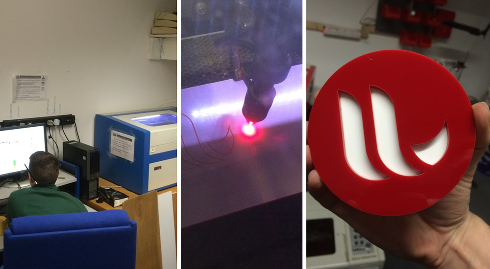
Playing with a laser cutter sure beats watching paint dry.
Once the paint was dry, we were able to do the final step - gluing the bases on to the stand. To be more secure, we decided to drill out 4 studs per board to screw them onto the backboard. Glue was still applied to ensure the whole board stayed flush with the wood. Admittedly, we inscribe our names in glue on the back of the Lego boards!
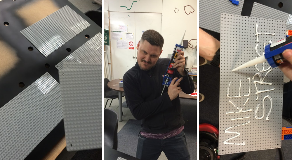
Glueing and screwing the lego boards into place.
Final Touches
With that, our device lab was complete. Being a design agency, Will insisted all of our Lego should be the same colour. We headed up to our local store and cleaned them out of red blocks and white arches! The arches are perfect for cable management and we picked up a handful of the smooth pieces, to give the blocks a professional finish.
The device lab now sits proudly in the corner. All the devices are plugged into an extension lead which turns on twice a day for an hour - just to keep the devices charged.
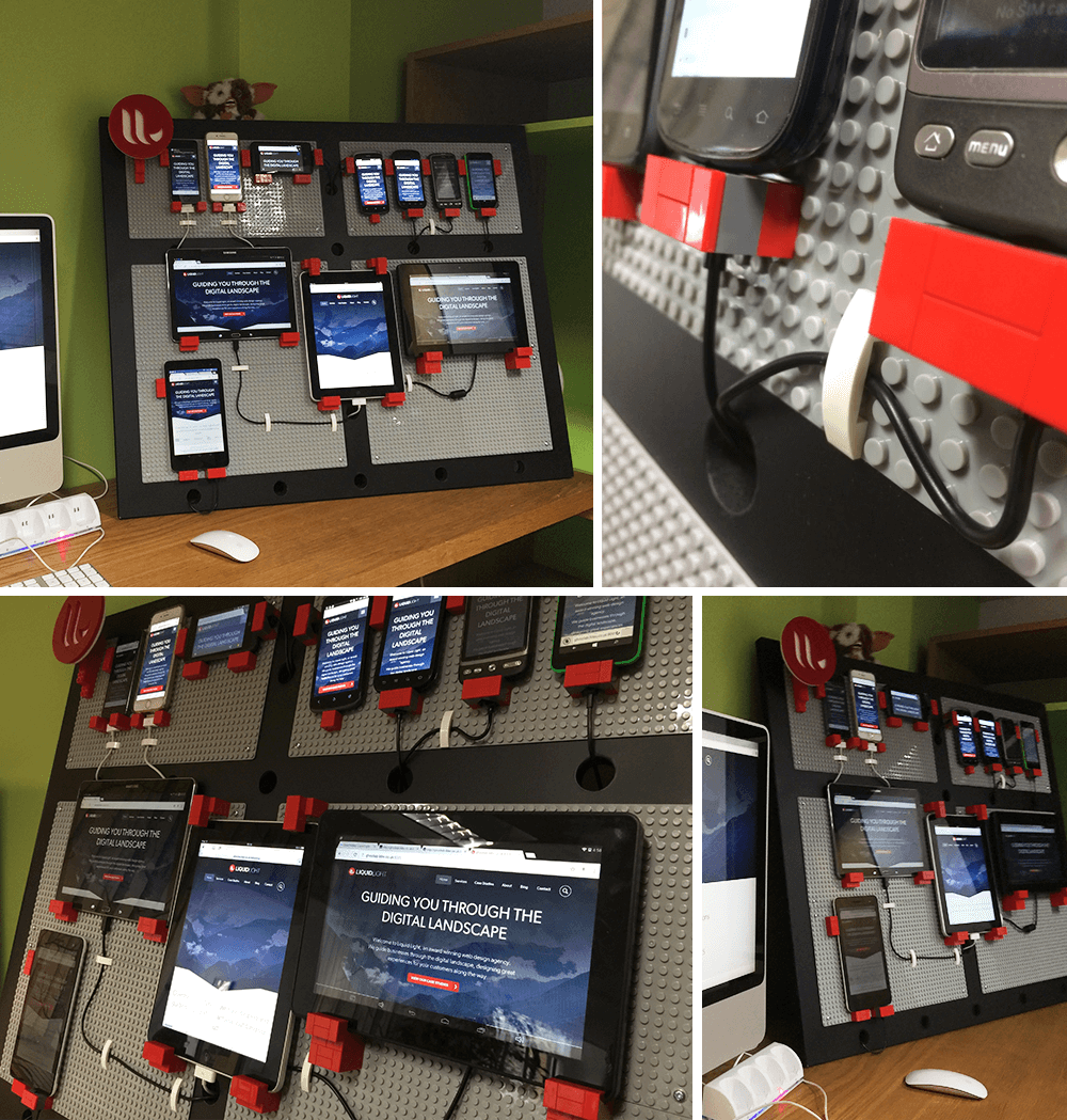
The finished device lab in its new home and ready for action.